MSEC / Other designs

Where itstarted.What else we studied.

The main design is now the 50K vertebral kit. This page keeps the first 50K render set, the purchased-donor compact, the Class 8 combination, the Habitat concept archive and the shared protection and autopilot studies.

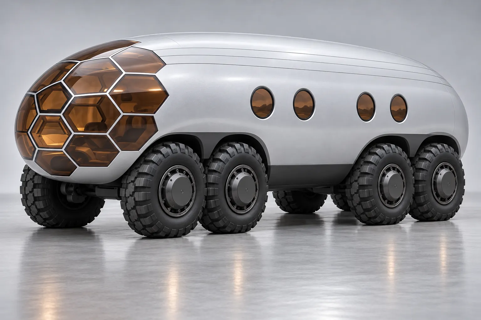
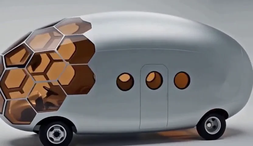
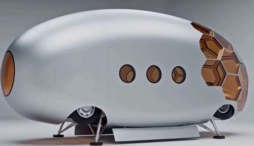
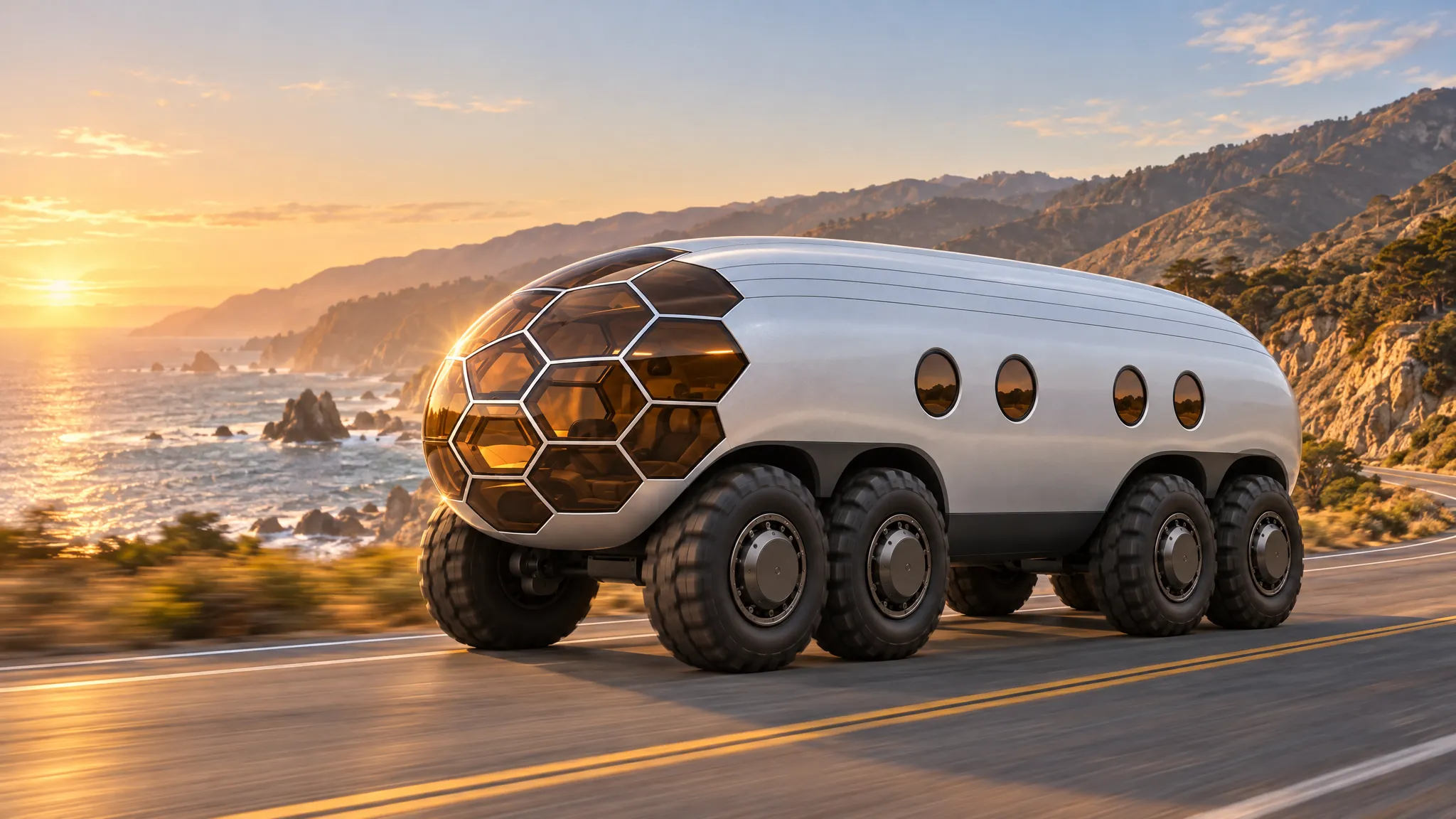
Archived concept render of a rounded silver MSEC capsule with warm copper front glazing and circular side windows
HABITAT ARCHIVE / V34BExterior concept · AI-generated
01 / Donor compactLower. Expand.20 × 8 × 8 ft stowed target · ≈26k GVWR
02 / Heavy<30 ft80,000 lb with a separate trailer
03 / ProtectionLayeredSelective armor + continuous RF boundary
04 / AwarenessOpen stackAutoware + independent safety control

Alternative design proposals, 29 October 2026; superseded as the lead design on 30 October 2026. Historical concept art illustrates the direction; dimensions, mechanisms and protective performance remain unverified.

30 October 2026 / First 50K render set

The 50K,
before the SKIF skin.

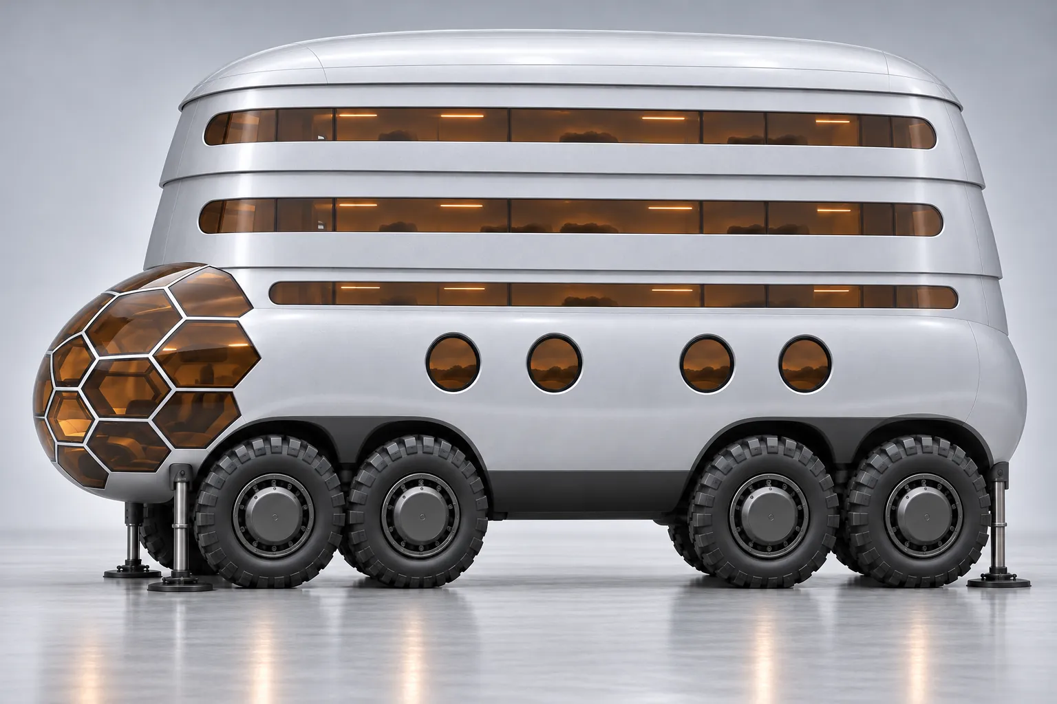
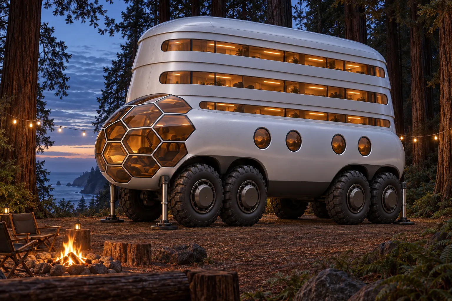
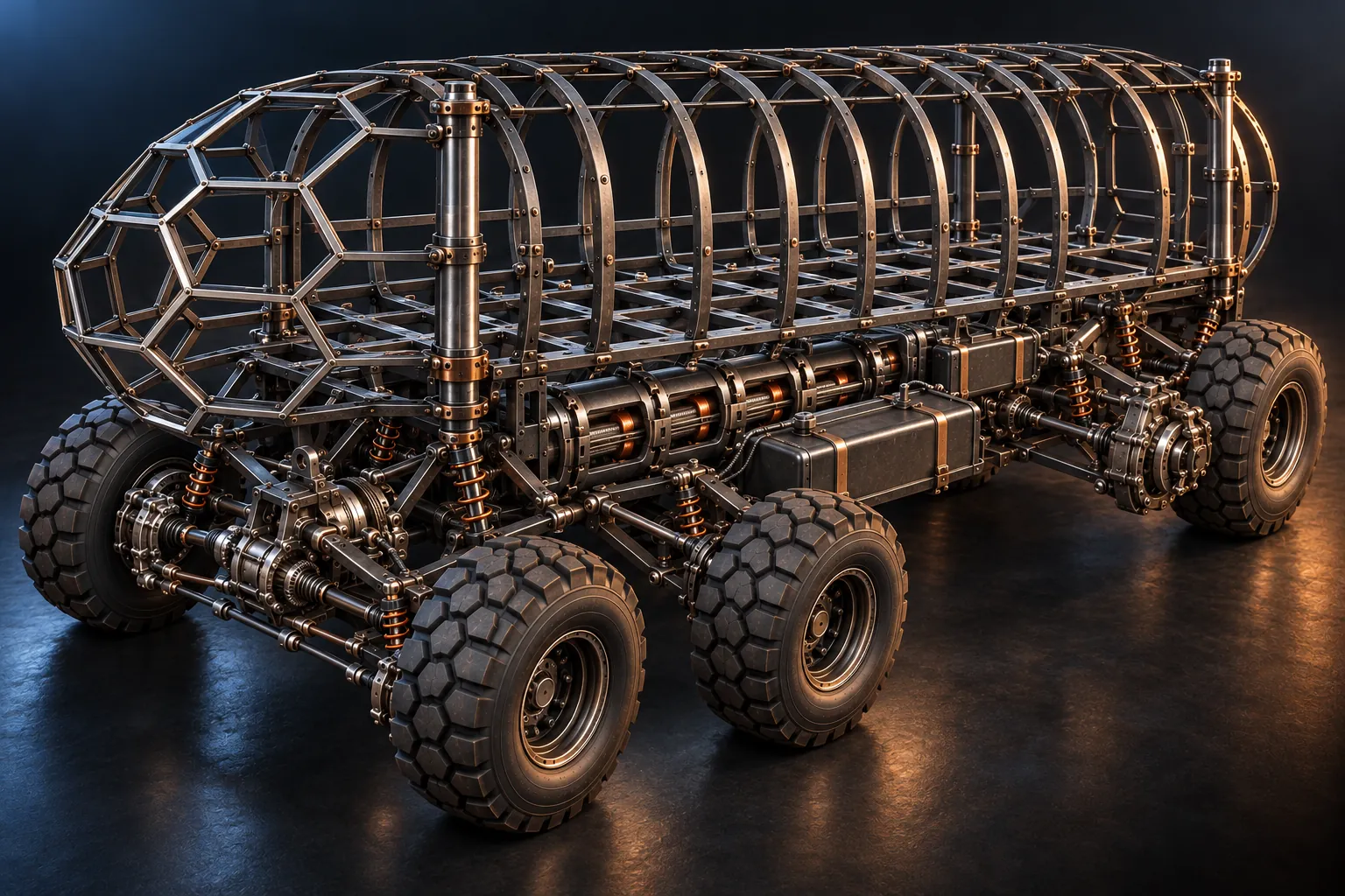
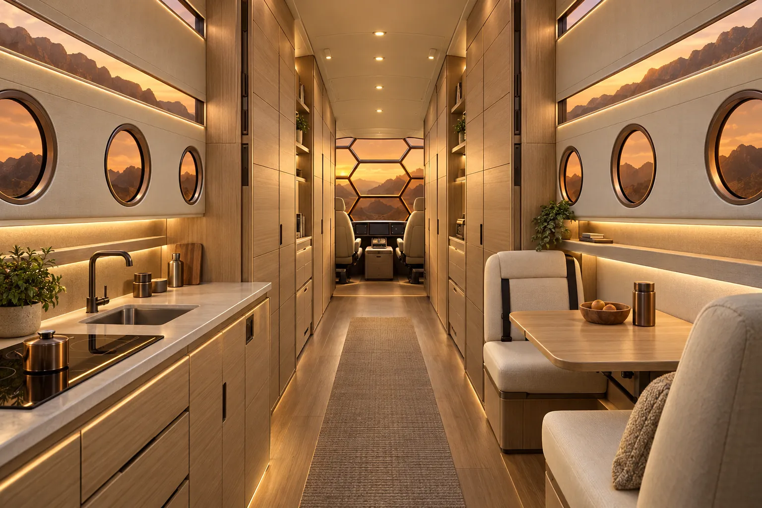
The first renders of the 50K vertebral kit used hexagonal copper glazing, round portholes and visible wall bands. The main design now uses SKIF’s gore-window rosette and one smooth skin over twelve-sided iron ribs. The chassis and numbers are unchanged.

Current direction / 29 October 2026

Two donor families.
Three body designs.

Our primary design is a roughly 26,000 lb medium-duty compact targeting 20 × 8 × 8 ft when stowed, with clearance margin. F-650 and equivalent donors remain candidates. The larger family is a Class 8 under 30 ft.

A / Primary · expanding compact

Low when stowed.
Room to rise.

A fixed lower tub, telescoping roof and overlapping rigid sliding panels. Raise slowly while stationary; lock at usable heights. Retract and mechanically latch before travel or dimension-limited parking.

Primary stowed target
<20 × <8 × <8 ft
Donor loaded rating target
≈26,000 lb

Length × width × height. Exact donor fit is unresolved: the cab, chassis and fittings must fit too. The primary must fit below 20 ft; under 22 ft remains only for the fixed tall alternate. A 7 ft height is not required.

See the roof states →
B / Alternate · fixed compact

Standing room.
Always ready.

The same short-wheelbase medium-duty family, with a fixed tall shell and no lifting roof. Keep the finished truck under 22 ft and accept oversized parking treatment.

Loaded rating target
≈26,000 lb
Carrier-height study
≤12 ft

Simpler shell joints and permanent headroom. Park on suitable permitted sites; a tall body does not have unrestricted parking rights.

Compact towing limits →
C / Larger donor · Class 8

Use the full
road envelope.

Already oversized for city parking: retain width and height for living space, with the powered truck/RV strictly under 30 ft. Keep its fifth-wheel and trailer-clearance needs in the layout.

Body width ceiling study
102 in
Overall height ceiling study
14 ft

California ordinary-road ceilings, subject to route restrictions and clearance margin. Approximately 80,000 lb is the entire loaded combination; the trailer adds length.

Heavy layout and loads →

A / How the primary body changes

One footprint.
A changing roofline.

Illustrative roof lift: 24–36 in above a 95 in stowed exterior height. Fixed width; no side slide-outs assumed. This is a mechanism study, with donor fit and standing headroom still to resolve.

Ford’s 2022 brochure lists 90.2–94.4 in regular-cab height and 95.5 in front-fender width: a possible starting envelope, with very little width margin before mirrors. Cabovers may save length but are not assumed lower. A 7 ft city height limit is tighter than this cab; lowering suspension is an unverified separate study. Preserve driving visibility, restraints, structural load paths and escape routes.

  1. 01 / Stowed and latchedUpper shell nests over the lower tub. Roof fittings fit inside the measured parking envelope; positive locks carry road loads.
  2. 02 / Slow, stationary expansionGuides keep the lift square. Obstruction detection, load holding and emergency stop protect the moving panels. No pressure operation during movement.
  3. 03 / Raised and supportedMechanical supports hold the roof. Qualified locked positions close weather, pressure and RF joints. Intermediate heights stay unpressurized unless separately engineered.
What counts as oversized? Santa Monica and other cities

Santa Monica Municipal Code §3.12.860 and the city’s current guidance say vehicles exceeding 20 ft long OR 8 ft wide OR 8 ft tall need an overnight oversize permit from 9 pm to 6 am. We target below those dimensions with margin. Commercial registration is ineligible for that permit.

Los Angeles’s Controller summarizes a different rule: over 22 ft long or 7 ft high in signed zones, 2–6 am. San Diego separately restricts RVs. There is no verified “most cities” envelope. Retraction addresses dimensions only; posted parking, RV use, occupancy and trailer restrictions still apply. Raising the roof changes the parked envelope.

Santa Monica municipal code · City permit guidance · Los Angeles Controller · San Diego city guidance · Ford donor dimensions
Checked 29 October 2026. Verified against the municipal code and city guidance. Fixtures and accessories count, except single-post radio antennas; trailers of any size are covered overnight.

Custom body, donor chassis or our own frame?

The registration baseline retains an identifiable titled donor chassis with a custom body and subframe. We will also study an owner-designed main frame for packaging freedom. A new frame does not automatically inherit the donor’s VIN, 26,000 lb rating or towing capacity.

California provides altered-vehicle and specially constructed vehicle routes. A new main frame needs its own DMV/CHP identity review, emissions determination and engineering/rating plan. The limited SB100 emissions certificates are not a blanket limit on every homebuilt registration. No custom-frame approval is established.

California DMV: altered and specially constructed vehicles

Another option: a customer-completed rolling kit

Supply a substantially assembled chassis and body, with the customer completing assembly and installing a specified compliant engine, ECU and matched emissions system. Study this alongside an OEM-chassis build; neither requires assuming an SB100 allocation.

A kit with a customer-installed powertrain has commercial precedent. Our exact 26k motorhome package still needs its manufacturer and registration roles defined. A missing battery or token final step is not an established exemption, and an engine certificate alone does not settle every vehicle-level requirement.

Custom 8×8: maximum weight at 20 ft or 30 ft?

With four axles and just 3 ft total front/rear overhang, the California general weight table permits 53,500 lb at 20 ft OAL (17 ft outer-axle span) or 60,000 lb at 30 ft OAL (27 ft span). These are illustrative custom layouts, not established chassis ratings.

Optimistic table bounds are 55,500 lb at a rounded 20 ft axle span and 62,000 lb at 30 ft span, but those leave no demonstrated allowance for tire/body overhang within the same OAL. Through 30 ft axle span, adding a fifth or sixth axle does not raise the table’s whole-group ceiling.

All figures are total loaded weight, not payload. Every consecutive axle group, tire/equipment rating and local/bridge restriction still applies. Eight-wheel drive itself grants no extra allowance. The primary compact target remains approximately 26,000 lb GVWR.

Caltrans axle-spacing weight table

Running gear: solid axles or independent geared wheel ends?

Compare a conventional solid driven axle with independent wheel suspension: a chassis-mounted differential drives each wheel through an articulated half-shaft. Optional reduction gears at the hub reduce upstream drive torque; a portal offset adds ground clearance but may compete with our low-height target. This military-style layout is an alternate study, not selected hardware.

At an illustrative 60,000 lb over eight wheels, static load is 7,500 lb per wheel. Suspension, wheel ends, shafts, steering and brakes need a coordinated design; no military donor part is assumed suitable merely by appearance.

Electroforming is a candidate for separate housings and covers, not a demonstrated process for an entire functioning axle. Pure nickel and ordinary iron/nickel alloys are magnetic. High-phosphorus nickel can be essentially nonmagnetic as deposited, but typical electroless coatings have low ductility and do not establish a road-rated structural alloy. Housing mass depends on stiffness and fatigue allowance; no complete-system weight saving is claimed.

Electroformed axle: how close can the weight get?

Our geometry-based solid-axle study uses 7,500 lb static per wheel, combined impact/braking assumptions and matched steel references. In the target iron-rich material scenario, a 160 mm tube needs 9.1 mm finished wall versus 8 mm steel. The modeled housing plus straight-shaft substitution adds about 28 lb to a 750 lb subtotal—roughly 4%.

Using a 180 mm tube gives roughly 2% extra in the target case; lower conservative allowables give about 9–14% across the two diameters. These totals include an assumed 441 lb common-parts allowance, not a weighed commercial axle, and exclude tires, suspension and steering additions. Retaining purchased steel shafts reduces the modeled penalty.

The independent geared-hub study separately estimates 344 lb for steel cases plus straight half-shafts, 354 lb in the target scenario and 387 lb in the conservative scenario. That excludes the rest of the suspension and drivetrain and is not comparable to a complete axle.

All material allowables are hypothetical inputs. The designs need thick-deposit fatigue/ductility evidence and detailed bearing, joint and gear alignment work. Iron-rich materials are not assumed nonmagnetic; no road-rated axle or complete-system weight is established.

A + A / B + B / C + C

Build a pair. Tow its twin.

Every variant aims to tow a matching second vehicle for more living and carrying space, or pull a compatible ordinary trailer. Each vehicle remains independently usable. Reserve frame-rated coupling, brakes and transport interfaces in both copies.

Compact: two fully loaded 26,000 lb trucks already total 52,000 lb before a carrier—above the diesel F-650 family’s 50,000 lb combination example. Reduced transport weights are necessary for that example.

Heavy: two assumed 26,000 lb vehicles plus an assumed 12,000 lb carrier total 64,000 lb, before extra cargo. A tall Class 8 on a carrier may exceed 14 ft; wheel-on-road towing needs its own engineered driveline, steering, braking and coupling solution.

Matching-pair towing is a design goal for all three, with no verified complete donor pair or tow system. Towing adds no rating: the first vehicle’s combination, axle, hitch, route and length limits still govern. Neither an 80,000 lb payload nor two 80,000 lb trucks is implied.

01 / The design archive

The capsule,
from every angle.

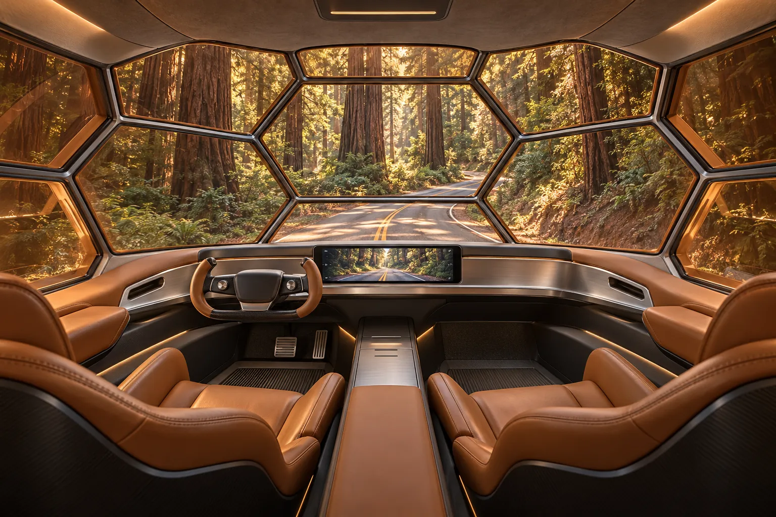
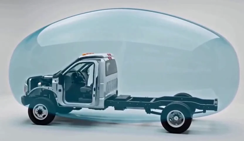
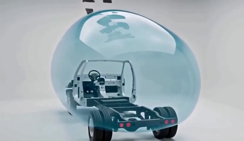
Recovered Habitat studies: the silver shell, copper glazing, open chassis and warm interior. The shared habitat work is now visible in the MSEC story.

The exterior in motion

Walk around the capsule.

The recovered 15-second orbit shows the front, sides, rear and parked posture. Generated geometry varies through the shot.

These are historical AI concept films, retained as design notes. They predate the primary retractable roof and do not demonstrate its mechanism. The current variant targets govern the design. Wheel retraction, pressure sealing, armor and shielding are engineering proposals.

02 / Protection by design

A protected core.
A continuous shield.

Put armor where it earns its weight. Keep the radio-frequency boundary continuous. Build the running gear for the loaded vehicle.

Protection architectureSection concept / not to scale
Four layers around the occupied capsule and a separately shielded equipment rackReplaceable exterior panels surround selective armor, the conductive environmental shell and a warm interior. All doors, glazing, vents and cables need their own boundary treatment. This diagram does not imply full armor coverage. SHIELDEDEQUIPMENT 01 / Weather skinReplaceable outer panels 02 / Selective armorThreat-specific assemblies 03 / RF boundaryHull, joints and penetrations 04 / Living spaceInsulation, finish, services Doors · glazing · vents · cables: continuity at every opening
Separate functions, engineered together. The armor arcs illustrate selected zones; the thin metal shell has no established ballistic rating.
A / Physical protection

Armor the vital zones.

Protect selected cockpit footwell, sill and bulkhead areas, plus a compact refuge and equipment zone. Specify tested panels, joints, glazing, mounts and fragment containment as an assembly.

Keep two exits with unpowered release, driver visibility, restraints, fire separation and inspection access.

B / Emanations security

Close the whole RF boundary.

Conductive hull, bonded seams, gasketed doors, conductive glazing, shielded vents and filtered service entries. Put radios and navigation antennas outside; isolate the equipment rack inside.

Design target: ≥40 dB from 30 MHz–6 GHz after assembly. No measured attenuation, EMP or TEMPEST certification is claimed.

C / Mobility

Severe service. Real load ratings.

Use compatible commercial severe-service tires, rated wheels, protected lines, a full-size spare and pressure/temperature monitoring. Study matched run-flat and central-inflation systems as upgrades.

Larger military-style tires change gearing, steering, braking, roof height and wheel closures. Michelin’s 45 in XZL example is limited to 55 mph and listed “Suitable for RV: No”; it is a comparison, not a selected MSEC tire.

Interior zoning proposal

Keep the heavy systems low.

Integrated cockpit forward. Shared living and services in the middle. A protected refuge and equipment zone near the load-bearing base. Final placement follows measured axle loads.

Conceptual top-down capsule interior zoningCockpit, living area and refuge form three zones. A service spine runs along one side; a main exit and independent escape hatch are marked on opposite sides. No dimensions or final furniture fit are implied.COCKPITSERVICE SPINELIVING / WORKINGREFUGE +EQUIPMENTMAIN EXITESCAPE

03 / Open autopilot architecture

See all around.
Build up to control.

Autoware and ROS 2 for the open software foundation. Vehicle-specific by-wire hardware and an independent safety controller connect the software to the truck.

Proposed sensor coverageCompact / top view
Eight exterior cameras, five radars, three LiDARs and dual GNSS antennas around the compact capsuleThe diagram shows planned sensor positions around an elongated capsule. Fields of view overlap, but complete detection coverage has not been validated. Twelve near-field ultrasonic sensors and an interior driver camera are additional components. FRONT 8 camerasSurround + forward detail2 GNSS antennasHeading + IMU fusion3 LiDARsRoof + two low corners5 radarsFront + four corners + 12 near-field sensors · wheel/steering feedback · driver monitorMounts, occlusion and coverage require vehicle-specific validation
Exterior sensors sit outside the RF shield. Cleaning, heating, calibration, timing and protected feedthroughs belong in the installation.

The full stack, including the hard part.

A rugged GPU computer handles perception and planning. A separate safety ECU supervises authority and faults. A supported by-wire kit translates commands to steering, brakes, throttle and gear, while preserving driver override.

Exact-donor actuation is still unresolved.

Dataspeed lists an F-600; that does not establish F-650 or Cascadia support. openpilot’s car list also does not establish an MSEC integration. Begin with sensing and logging while the physical control interface is specified.

  • PerceptionCameras + radar + LiDAR, with synchronized health monitoring.
  • Position and planningGNSS/IMU/wheels + surveyed maps + truck-specific motion model.
  • Independent supervisionWatchdog, physical controls, fresh feedback and a defined service-brake stop path.
  • Local, isolated controlSeparate vehicle network, signed updates and no cloud dependency for driving.

Proposed full equipment allowance: $40k–100k, plus integration, validation and approvals. Nominal installed mass: 250 lb. These are planning allocations.

01 / InputsSense + localize
02 / Open softwarePlan + control
03 / Two control gatesSoftware + safety ECU
04 / Vehicle-specificBy-wire + OEM systems
FIRST / AWARENESS

Surround sensing

Visibility, recording, obstacle warnings and sensor-health display. Driving stays with the human.

NEXT / CONTROLLED PROPERTY

Supervised crawl

Parking and recorded-path research at ≤5 mph, dry daylight pavement, no trailer, seated driver and hold-to-run control.

LATER / SEPARATE VALIDATION

Road assistance

Lane keeping and adaptive cruise need exact-donor integration and a resolved regulatory path. No driverless-road capability is claimed.

Components, stopping space and integration requirements
Proposed full compact research installation. Supplier compatibility and software versions must be verified.
SubsystemAllocationIntegration
Autonomy computer1 rugged x86-64 + NVIDIA GPU, 64 GB RAM, 2 TB NVMePinned Autoware release and supported ROS 2/driver versions.
Safety and actuationIndependent safety ECU + exact-donor by-wire kitSeparate watchdog/power, manual override and supplier-defined stop on faults.
External sensing8 cameras, 5 radars, 3 LiDARs, 12 ultrasonic sensorsCleaning, heating, synchronized timestamps, calibration and occlusion checks.
Position and motionDual-antenna GNSS, IMU, wheel/steering/brake/gear feedbackLiDAR/map cross-checks; refuse engagement on inconsistent localization.
Driver and controlsIR driver monitor, display, alerts, physical arm/override/hold controlsDriver authority and an independent emergency path.
Power and cooling600–1,000 W design budget; protected DC/DC + essential-control backupFuses, transient protection, thermal monitoring and safe reserve on power failure.
Network and recordingPTP switch, isolated CAN/J1939 interfaces, removable storageSeparate house/vehicle networks; authenticated maintenance only while stopped.
Maps and simulationLanelet2, point clouds, rosbag2/MCAP, CARLA/AWSIMActual truck dimensions, steering/braking model and fault/scenario replay.

At 5 mph, an assumed 0.8 s delay, 2 m/s² net deceleration and 2 m margin require about 5.0 m / 16.5 ft of verified stopping space. This is a level-ground calculation; real load, slope, traction and sensing performance set the usable envelope.

No engagement with deployed legs, unlocked wheel covers, an unverified cabin connection or a trailer in the first control stage. Automatic parking begins only after bench, simulation, fault-response and closed-site validation.

Autoware documentation ↗ · By-wire vehicle compatibility ↗ · California DMV requirements ↗

04 / Every pound has a place

Protection spends
payload.

The nominal protection, mobility and autonomy package adds 1,800 lb. Start with a loaded vehicle weight that already includes the people, water, batteries and gear.

Selective armor, shielding, mounts and hardware1,200 lb
Wheel / tire / mobility changes, net increase350 lb
Autopilot sensors, controls, power and cooling250 lb
Nominal added package1,800 lb

Protection example: 6 m² opaque panels at an assumed 38 kg/m², 0.8 m² glazing at 70 kg/m², and 260 kg of mounts, backers, RF and emergency hardware. These masses imply no ballistic rating.

Check the front axle before adding more.In the illustration, 2,700 lb of gross headroom leaves only about 229 lb on the steer axle. Position matters as much as total weight.

Full-envelope armor needs a separate mass study. Larger tires do not raise GVWR or axle ratings.

Try the compact weight budget

Illustrative default: 21,500 + 1,800 = 23,300 lb, leaving 2,700 lb below 26,000 lb. No actual truck has been weighed.

Axle positions and rating assumptions

One aggregate center for the whole package; base rear load = base total − base front. Actual labels, corner weights and each component’s position govern.

Checks gross and two-axle arithmetic only. Tires, wheels, mounts, brakes, center of gravity and towing need their own engineering.

05 / Vehicle envelopes

Two donor families.
Shared foundations.

Expanding and fixed bodies share the compact donor family. The larger Class 8 uses its own full road envelope. These earlier sketches show donor packaging, not the primary roof mechanism.

01 / Powered vehicle envelopesConcepts · same length scale
Fixed compact alternate under 22 feet; heavy MSEC truck under 30 feet Side-view packaging sketches compare a compact rounded truck habitat with a conventional sleeper tractor. The heavy tractor retains a fifth wheel for a separate semitrailer. These are concept envelopes, not fabrication drawings. COMPACT Fixed alternate · F-650 26,000 lb truck GVWR Fixed alternate: under 22 ft HEAVY Class 8 sleeper tractor 80,000 lb with trailer 28 ft 2 in example · under 30 ft required Fifth wheel Fixed compact alternate under 22 feet and a 28 foot 2 inch heavy tractor example, on the same length scale FIXED ALTERNATE / F-650 HEAVY / CLASS 8 SLEEPER
Length targets and calculated envelopes. The final custom hull, mounts and trailer clearance remain to be engineered. No donor is selected.
01 / COMPACT DONOR FAMILY

Two compact bodies.
One donor family.

Prioritize the expanding body within 20 × 8 × 8 ft stowed, with margin; retain the fixed tall body as an alternate. Both use the short medium-duty category near 26,000 lb GVWR.

Primary stowed envelope
<20 × <8 × <8 ft
Truck loaded rating target
≈ 26,000 lb
Towing and transport conditions →
02 / HEAVY COMBINATION

A common tractor.
A much bigger envelope.

A tandem highway sleeper tractor keeps the fifth wheel and puts major cargo on a semitrailer. Cascadia / DT12 is the first used-market search.

Powered truck/RV length
< 30 ft
Total loaded combination
≈ 80,000 lb
Layout, axle spacing and donor category →

01 / Compact MSEC

Keep the footprint.
Reserve room in the weight budget.

The primary is a short-wheelbase medium-duty truck near 26,000 lb GVWR, automatic or clutchless AMT, targeting under 20 × under 8 × under 8 ft stowed. F-650 and equivalent low-maintenance donors remain eligible; no complete fit is verified.

Both compact bodies target matching-pair towing. The larger rig should also carry or tow a compact. The hitch load uses some of the towing truck’s own weight allowance.

Two full compact MSECs already weigh 52,000 lb. A transport trailer adds more. That exceeds the diesel F-650 family’s 50,000 lb combination envelope, so compact-to-compact towing depends on reduced transport weights.

Ford’s current family guide gives a 50,000 lb diesel combination envelope and 37,000 lb for gas. The exact used donor must support its own rating; neither figure is a guaranteed trailer capacity.

GVWR is the loaded truck ceiling. GCWR is the loaded truck and trailer ceiling. A suitable license changes neither rating.

Ford medium-truck towing guide ↗

Explore compact-to-compact towing

Assumed weights, including a transport trailer. This checks gross arithmetic; it cannot establish towability.

Reduced example: 20,000 lb towing truck + 22,000 lb carried MSEC + 6,000 lb carrier = 48,000 lb combined. Both full, with that carrier: 58,000 lb.

Carrier tare and hitch percentage are assumptions. Trailer balance, individual axle/tire loads, coupling, frame, brakes and drivetrain procedures need their own checks. Flat towing is unverified.

Being carried changes
the height problem.

Reserve structural tie-down points and transport clearance while the compact body is still being designed.

Can the larger rig carry a full compact?

That is the goal: reserve trailer capacity for a compact weighing up to 26,000 lb, plus the trailer’s own weight and equipment. Actual axle balance, point loads and clearances still decide whether a particular carrier works.

How tall can the compact be on a carrier?

A 12 ft compact on an assumed 18 in loaded low deck reaches 13 ft 6 in. A 13 ft compact on a 24 in deck reaches 15 ft, above California’s ordinary 14 ft ceiling. Retraction may improve the primary body’s transport height. Study the fixed compact at most 12 ft tall for carrier compatibility; the final body and lowboy are unselected.

What stays part of the MSEC design?

The cockpit remains inside the intended pressure hull. Cab and habitat form a rigid, detachable assembly in road use, supported to accommodate chassis twist. Pressure rating, joint construction and service separation remain engineering work. A factory sleeper is only a starting envelope.

02 / Heavy MSEC

Start with the truck
built to pull a semi.

First search: Cascadia 126, DD15, clutchless DT12, tandem rear axles and a 60–72 in sleeper. Keep the finished powered section under 30 ft; let the trailer supply the extra capacity.

A common donor

The 126 sleeper market is much broader than the shorter-nose 116 market. Include both, and compare Volvo / I-Shift on condition and delivered cost.

A small living space

A 72 in sleeper offers a compact bed/dinette, galley and toilet study behind the cockpit. A day cab with an 8 ft custom habitat is the roomier, more demanding alternative.

A retained fifth wheel

The custom hull must clear the trailer through turns, pitch and roll. The calculated sleeper example leaves 82 in from the body’s rear to the kingpin.

02 / The 80,000 lb road-loading example12,000 + 34,000 + 34,000 lb
Five-axle layout with 12,000 pounds on the steer and 34,000 on each rear tandem In the shorter example the first-to-last axle span is 54 feet. The rear four axles span 36 feet 2 inches, using California's two-tandem exception. The alternative extends the trailer axle position three feet rearward. Truck/RV envelope 12,000 lb34,000 lb 34,000 lb 54 ft outer axle span
61 ftTotal combination example
54 ftFirst-to-last axle span
41 ft 8 inTrailer overall example
28 ft 2 inPowered truck example

Tandem-exception example: 36 ft 2 in across the two rear tandems permits 34,000 lb on each under CVC 35551(b). All ten consecutive axle groups pass.

80,000 lb is the whole combination.

At the illustrated loading, 46,000 lb rests on the truck’s axles, including the trailer’s kingpin load. The other 34,000 lb rests on the trailer’s axles.

A planning example uses a 26,000 lb uncoupled truck plus a 54,000 lb loaded trailer. A 20,000 lb kingpin transfer produces the 46,000 / 34,000 split. The kingpin load is counted once.

Unverified planning allowance: 18,000–22,000 lb complete sleeper tractor, plus 4,000–8,000 lb net conversion addition. The actual build, fluids, people and belongings need a component budget and axle scale weights.

A length calculation is not a rated vehicle.

The 28 ft 2 in truck assumes a 240 in wheelbase to the tandem midpoint, 52 in tandem spacing, 48 in front overhang and 24 in behind the last drive axle. The 61 ft rig uses an approximately 42 ft semitrailer.

The longer 64 ft alternative passes the general chart without the two-tandem exception. Both need exact donor/trailer geometry, equipment ratings and load placement. An ordinary lowboy may be longer or taller than this envelope.

Use the ordinary 65 ft combination envelope for planning. Registration, kingpin dimensions and actual route access control; a converted RV must not assume every freight-tractor exemption applies.

6×6 is not needed for this weight target. A common 6×4 tandem highway tractor is the practical starting point. Protection and severe-service running gear are separate packages on the chosen donor; their mass and compatibility remain part of the vehicle budget.

03 / Used-market direction

Search the common fleet.
Select the individual truck.

A dated market snapshot supports the donor category. It does not establish a finished under-30-ft conversion, its condition or its ratings.

Advertised evidence checked 27 October 2026. Prices exclude tax, delivery, repairs, conversion and trailer.
Search or leadAdvertised evidenceWhat it tells us
Cascadia 126 sleepers ↗About 3,300 category listingsA broad donor market.Includes new, manual, auction and defective trucks; these are not all eligible candidates.
KDH, Lynwood CA ↗2020–2021 Cascadia 126 sleepersSeven listed; call for price
About 431,000–492,000 mi
Nearby inspection pool.Exact AMT, dimensions, labels and condition need checking per truck.
Big Rig Companies, MN ↗2021 Cascadia 116 / DT12$38,900
665,715 mi
A sub-$40k AMT sleeper example.High-mileage lead; overall length, wheelbase and complete ratings unverified.
Belle Way, IN ↗2021 Cascadia 116 / DT12$48,900
514,867 mi
A higher-price comparison.OAL and ratings unverified; no budget increase is adopted.

The shorter-nose 116 category returned 118 listings. Compare delivered cost and service records before paying a premium for its shorter hood. No truck is selected and no seller has been contacted.

04 / Design basis

Make the limits
part of the design.

The architecture is chosen for further design. A purchase decision still depends on the actual truck, completed body and trailer.

  1. Verify the finished envelope.Measure all permanent projections, trailer swing, frame articulation and engine service motion. Wheelbase alone does not establish overall length.
  2. Budget every load.Check truck and trailer ratings, individual axles, tires, coupling and every consecutive axle group. Leave practical weight margin for use.
  3. Keep the integrated cabin.The cockpit pressure hull and rigid, detachable cab/habitat assembly remain requirements. Pressure, mount and joint engineering are unverified.
  4. Plan the actual California operation.Budget for the appropriate Class A license for heavy cargo trailers. Confirm housecar registration, emissions, insurance and route access for the finished rig.